
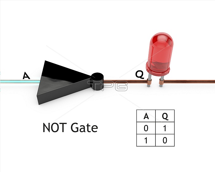
NOT logic gate, diagram. Logic gates are electrical circuits that are wired so as to produce a specific output according to logical rules. The diagram shows an input (A) and an output (Q). A NOT gate has one input. It will output the opposite of this, as shown in the table at lower right. The input here is on, with the LED (light-emitting diode) at right in the off (unlit) state. The shape of the logic gate shown here is that of the NOT symbol used on circuit diagrams. For a series of diagrams of the seven basic logic gates (NOT, OR, AND, NOR, NAND, XOR and XNOR), see images C045/9800 to C045/9806.
| px | px | dpi | = | cm | x | cm | = | MB |
Details
Creative#:
TOP24609545
Source:
達志影像
Authorization Type:
RM
Release Information:
須由TPG 完整授權
Model Release:
N/A
Property Release:
N/A
Right to Privacy:
No
Same folder images:
 Loading